05.1100
Earth-Motion Detector using Diamagnetic Levitation and
a Capacitive Sensor
Randall D. Peters
Physics Department
Mercer University, Macon, GA
Copyright July 2012
Abstract
Described is a compact, sensitive instrument that functions as a tiltmeter
and/or accelerometer that is well suited to quantitative studies of earth
motion.
Background
Recent years have witnessed a diligent search for small accelerometers that
are also highly sensitive. The task is made difficult because the sensitivity
of such an instrument, whether functioning as a tiltmeter or as a seismometer,
depends inversely on the square of its natural frequency. Success in these
endeavors has been elusive because of two factors. First, the eigenfrequency
of a mechanical oscillator is inversely dependent on the mass of the unit.
Therefore it is necessary, with significant decrease in size, that the effective
spring constant of the oscillator become exceedingly small. Efforts to obtain
a (useable) small restoring force have encountered the second prohibitive
factor; i.e., long-period, low-energy oscillations are prone to`latching'
against oscillatory motion because of friction, whether of internal or external
type. Internal friction types, that result from damping anharmonicity' [1],
can impose serious performance limitations.
Diamagnetic Levitation
Also in recent years there have been increased efforts to try and minimize
friction limitations by means of magnetic suspension. The earliest scientific
studies of this type were conducted by Prof. Jesse Beams at the University
of Virginia. He used electromagnetic field feedback circuitry to eliminate
levitation instability associated with Earnshaw's theorem. More recently,
it was found that stable equilibrium without feedback is possible using pyrolytic
graphite (PG) plates with rare earth magnets. Even some pencil leads can
be supported above various combinations of such magnets. A seismometer of
this diamagnetic type has been built; whose inertial mass motion is monitored
with an optical sensor [2].
The present author's opinion, based on about two decades of intense study
of mechanical oscillators- is that only two sensor types are truly viable
for use with seismic instruments of this type- optical and capacitive. Because
of his invention of the first fully differential capacitive sensor [also
called symmetric differential capacitive (SDC)], efforts were mounted to
build the instrument that is now described. A small rod is not compatible
with capacitive sensing, but PG plates can be used, as illustrated by Fig.
1.
Figure 1. Photograph of a thin pyrolytic graphite (PG) plate resting
in one of the two equilibrium positions that exist above a three magnet set
(at an altitude of about 1 mm above the top plane of the magnets). Each of
the three rare earth (Neodymium) rectangular parallelipiped magnets is of
size (in inches) 2 x 1/2 x 1/4.
Configuration for the present prototype
For the equilibrium shown in Fig. 1, each magnet must be polarized perpendicular
to the 1/4 in dimension. By their mutual attraction, the three are held together
very strongly in the arrangement pictured (total size 2 x 1&1/2 x 1/4).
As such, the top magnetic individual pole labels are either N, S, N or S,
N, S-either of which is stable. The magnets shown were purchased commercially
[3]. The PG plate from which the instrument parts were fabricated were also
bought from the same company. It was of dimension (in mm) 32 x 32 x 0.75.
For the pair shown in Fig. 2 that follows, the plate was first cleaved with
a sharp knife to form two (approx. equal) pieces of thickness 0.375 mm. From
one of these pieces the individual pair of parts were then obtained by
`snap-breaking' with the same knife, to yield the smallest dimension (approx.
8 mm). A separation distance of 8 mm between the two plates was also sought;
however, its attainment proved challenging because of the small size of the
parts, including the copper wire which was superglued to them. Such deviations
from ideal have never been of great significance to SDC sensor types, which
are very `forgiving' of many construction imperfections.
As described in one of the author's SDC patents [4], a moving electrode array
yields higher sensitivity as compared to a single moving electrode, such
as the one shown in Fig. 1. Thus for the present instrument, two PG plates
were chosen, with a fixed spacing between them that corresponds to the spacing
between the equilibria shown in Fig. 1. Fig. 2 shows the diamagnetic levitated
pair resting in equilibrium above the magnets.
Figure 2. Photograph of the bottom part of the instrument, which uses
two PG plates to form the moving electrode set of an SDC array (in levitated
equilibrium at the time of picture taking). In the bottom photo (different
'highlighting' than the top photo) the small copper wire that was glued to
the plates is barely visible. Also very visible are the aluminized tape strips
that were stuck onto the magnet set with a gap between them to form the `drive'
electrode pair of the SDC sensor.
As will be shown from data records that follow, the equilibrium was found
to be stable in time and essentially harmonic (i.e., described by a parabolic
potential energy). The natural frequency of the motion was measured from
oscillatory free decay records to be 0.416 Hz.
The `sense' electrodes were fabricated from pc-board material and the array
is shown in Fig. 3.
Figure 3. Top component of the instrument, showing the sense electrodes
(upper photo). To hold the electrode structure in place above the magnets,
two steel nuts were superglued to the bottom of the pc-board (lower photo).
The penny was included with the picture for visual demonstration of size.
Fully assembled instrument
Figure 4. Top view photograph of the fully assumbled instrument. The
four wires attached to the instrument communicate with an analog type SDC
electronics box [6].
A given one of the two drive wires is connected to its associated aluminized
tape segment by means of a small (short, and soldered to copper wires elsewhere)
steel wire having a loop on one end. The loop is held in place by attraction
to that part of the magnet that is immediately under the wire's contact point
on an end of the segment.
For the present work, output voltage from the box was fed to a 24-bit usb
type analog to digital converter [7].
Example data records
Shown in Fig. 5 is a record that illustrates the sensitivity of the instrument
to tilt. It should be noted that this instrument, like all sensitive devices,
is influenced greatly by air currents. Thus for the records that follow,
the unit was placed under a small, inverted plastic container of the type
food comes in.
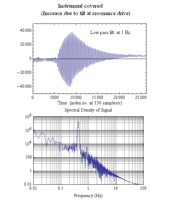
Figure 5. Example of tilt drive at resonance (region of increasing
amplitude), followed by a free decay. Low pass filtering with a cutoff frequency
of 1 Hz was used to effectively remove from the time record the influence
of some otherwise substantial 60 Hz pickup noise (due to less than desirable
shielding against the building's electrical mains).
The drive was by means of tilt change of the instrument due to deformation
of the concrete basement slab on which the author stood. With feet widely
separated on somewhat opposite sides of the instrument, body weight was
transferred back and forth from one foot to the other, at a frequency close
to the instrument's resonance frequency. The arrangement was similar to that
of a previous experiment involving a VolksMeter [8]. Based on the known
parameters of that case, a value for the instrument's calibration constant
was estimated at 1 ×10⁸ counts per radian (about one twentieth
that of the VM). Being a rough value based on comparison rather than a direct
measurement, the accuracy of this number should be viewed only as an order
of magnitude estimate. Even if the actual sensitivity, which is not by direct
means easily measured, should prove to be only ten million counts per radian,
the instrument is still sensitive enough to warrant further study of its
potential to compete favorably with other types of seismic instruments.
Shown in Fig. 6 is a record that illustrates the `purity' of the instrument.
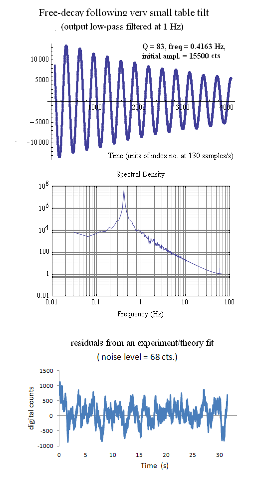
Figure 6. Free decay to which a theoretical fit was generated.
By trial and error adjustment of the theoretical parameters (using Excel),
the residuals (difference between experiment and theory) were minimized to
the level shown in the lowest part of the figure. The indicated noise level
of 68 counts compares favorably with that of other (large) seismometers.
The quality factor of 83 implies that damping is exceedingly small, even
though the inertial mass of the instrument is also indeed very small (roughly
2 g, based on the known density of PG material and the dimensions of the
oscillating mass). Surprisingly, the spectrum is virtually free from harmonic
distortion. Such a high level of linearity has been rare with the many other
mechanical oscillators that the author has studied!
Seismology purists would not accept this prototype as a viable horizontal
seismograph, since it is not dampened close to critical at Q = 0.707. The
author has nevertheless demonstrated that much valuable earth data can still
be extracted from records collected with the instrument, by working with
power spectral density calculations [9], as opposed to paying attention only
to temporal records. Moreover, it may be possible to lower the Q to an acceptable
level using eddy currents, by attaching aluminum foil to the plate pair on
both ends. And then have those move over an additional pair of small round
magnets placed at the ends of the present magnet assembly. Yet another idea
possibly worth entertainment would be to immerse the whole unit in mineral
oil. Viscosity of the oil would provide significant damping, and perhaps
its influence on electrical properties would not be overwhelmingly detrimental.
This thought derives from knowledge of the fact that some computer systems
have been successfully immersed in this way, to improve heat transfer away
from otherwise critical components.
References
[1] Article ``Anharmonic oscillator'', 10th ed. of the McGraw Hill Ency.
of Science and Technology. Also mentioned online at
http://chemwiki.ucdavis.edu/Physical_Chemistry/Quantum_Mechanics/Quantum_Theory/Trapped_Particles/Anharmonic_Oscillator
[2]
http://www.jsasoc.com/diamagnetic_suspension_seismomet.htm
[3] K&J Magnetics, online at
http://www.kjmagnetics.com/categories.asp?gclid=COW_yd-fhbECFdKR7QodKnew2A
[4]
http://www.google.com/patents/US5461319
[5]
http://telatomic.com/mechanics/sensor.html
[6] Previously sold by Tel-Atomic Inc. but no longer available for purchase.
This support electronics used a `chip' (Ne5521n) that is no longer manufactured,
following a factory fire. Electronics support for SDC sensors is now provided
by packages using the Analog Devices AD7745 capacitance to digital converter.
Some examples of its use are to be read online at
http://symcdc.com
[7] Sold by Symmetric Research
http://symres.com
[8] seismograph described at
http://rllinstruments.com
[9]
http://faculty.mercer.edu/peters_rd/psd-tutorial/psd.html
File translated from TEX by
TTH,
version 1.95.
On 6 Jul 2012, 14:39.